SWR METER
BUILD YOUR OWN STRIP LINE SWR METER
The text of this project should be read in conjunction with STANDING WAVES in the info section. You should also note, I have used the term "striplines". Technically striplines have a ground plane on both sides and those here are technically micro-striplnes because they only have one.
Here is a way to build your own accurate homebrew SWR meter and customise it to your own needs. It costs only a few dollars to add extra frequencies and other functions such as RF Volts. You can make your own pickups for HF, VHF, UHF and higher. With a bit of messing around and matching with a few resistor values, it can also be used to measure power levels or RF voltage.
BEFORE STARTING
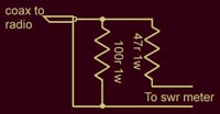
To be making a SWR meter, I needed something to test it as I went. The obvious choice is a radio but I needed to be able to test infinite SWRs both open and short circuit. Either might blow up a radio so I built the following short attenuation testing circuit. With this circuit I could get the meter going for UHF using an old 5w CB radio I don't use anymore and on 2m I could use a 5w handheld. Since it is forward and reflected power, at the strip lines, we are looking for, any attenuated signal will do. I used some two watt carbon film resistors I had knocking around. They have to absorb 5 watts but only for a second. I did cook a few and warmed a few up but they are cheaper than a radio. (Do not use high power WIRE WOUND resistors.) Beware also of some high power carbon film resistors. They can also be "wound", introducing more inductance. Note, there will be inductance anyway by virtue of their length. If in doubt, buy a couple of extra and scrape the paint off one. A couple of 47 ohm 1w resistors in series can be used instead of the 100 ohm or a couple of 220R in parallel. It really doesn't matter. |
|
Just like "db", "SWR" is a comparrison value. It says nothing about how much power is travelling in either direction. The value will be the same at 100mW or 1kW.
In the worst case scenarios, a short circuit means the radio is still working into at least 32 ohms and a maximum of 100 ohms with a complete open circuit. In these cases the forward and reflected voltage and/or power should be the same.
THE ONLY WAY TO MEASURE SWR IS WITH (MICRO)STRIP LINES - SEE WHY A BRIDGE DOESN'T MEASURE SWR. A bridge is two sets of series components with a BRIDGE across the central connections. Micro-stripline SWR pickups are NOT bridges.
HOW TO DO IT
The first thing to do is decide what frequencies we want to use the meter for. It is pretty useless to measure several Gigalitres of water with a medicine glass just as a few millilitres are impossible to measure with a flow meter suitable for Gigalitres. You wouldn't even get it wet. The meter described here works from about 28MHz through to 430MHz with 5 or 10 watts required at 28MHz and only a watt or so at 430. For a better HF meter, all you have to do is make it longer OR use an op-amp to amplify the signals. Given the length of the strips, this metre should work up to 1.4GHz (200mm wave length/4=50mm long) but I wouldn't use it at over 430MHz (except perhaps UHF CB). At 144MHz it needs about 2 watts or so. You need to watch the meter itself though. The strip lines themselves are suitable for hundreds of watts but the meter will burn out with too much power.
Materials:-
1) A BNC chasis socket and chasis plug or similar.
2) A couple of BAT out of hell diodes like BAT 81, BAT 42 or BAT something else.
3) A small piece of double sided PCB, 1.6mm thick and 50mm x 30mm.
4) A couple of small caps from about 220 pf to 1n, it doesn't really matter.
5) A single or double ganged pot (anywhere from 1k to 10k) linear or log.
6) A DPDT switch. Better, a 4 or 6 position double pole switch.
7) Some twin shielded audio cable.
8) Both a 3.5mm stereo jack and chasis socket.
9)
Some PCB etch like Ferric chloride or Ammonium persulhate. I have even
done it with Nitric Acid. You can also simply scrape the copper away
with a hacksaw blade.
10) A 100uA panel meter or similar.
11) Possibly a multi-position switch and a few attenuating resistors.
BOARD DIMENSIONS
All of the boards I make are 30mm wide but this is not really any sort os strict rule. For 6m to 70cm, 50mm long works well although more power is needed at 50MHz than 430MHz. I also use one 30mm x 30mm for the 70cm end and a board 150mm which works wuite well down to 40m.
CONSTRUCTION
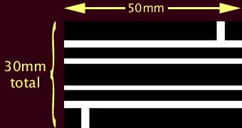
On one side of the PCB, etch, cut or grind the pattern below. Simple instructions can be found on the making PCBs page. The black areas are the copper while the white areas are etched away. Only a few values are critical but both sides should be the same. The central transmission line needs to be 6mm wide (on 1.6mm PCB) so that a 50 ohm transmission line characteristic is maintained through the meter. This is not all that important because the lines should be well less than ¼R.
The gap between the central micro-stripline and pickup strips needs to be as close as you can manage and also, more critically, as close to the same as you can manage. The smaller the gap, the harder it is to get them the same but I try for 2 mm. I made three before I was satisfied that I had them close enough. With a gap of only .5mm, the pickup side will handle kilowatts at 50Ω.
The distance between the strip lines to the ground on either side needs to be about the same on both sides but is not so critical. Even though the permittivity of fibreglass is around 4 or 5, the capacitance to ground through the board will still be much greater than to the sides.
Not only is the central conductor part of a 50 ohm transmission line, the pickup strip lines are also transmission lines and need to be correctly terminated at one end. The characteristic impedance for a micro-stripline is:-
Z0 = √L/C = 377 x (t/w) x Er-0.5
where t/w is the ratio of thickness of the material to width of the strip (so inch, mm or cubits doesn't matter) and Er is the relative dieletric constant of the material which for firbe glass PCB circuit board is about 4.5.
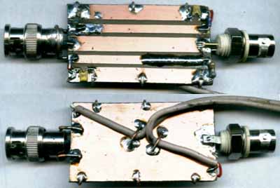
Once done, populate the board as shown below. If you are confident enough with SMD, the tracks shoud be close enough to use them. This makes a very neat little unit.
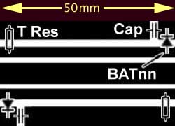
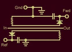
The ground on both sides of the PCB also need to be suitably connected. If you have some copper foil, it is best to wrap some along the entire length of both sides. I didn't have any at the time so used 3 fairly thick pieces of bare copper wire as shown in the diagram below.
The terminating resistors are critical but only in so far as they should be the same and somewhere near the correct terminating value for the width of the pickup strips. Correct SWR readings can be obtained with just about any resistor from 10r to 1k0 but more power may be needed. The diodes should be of the BAT variety, almost any number will do but the faster the better. BAT 81s are best. The bypass caps can be almost anything from 50p to 1uF but need to be plate type and NOT wound such as polyester ie. non-inductive. I tried putting a 220p on one side and a 10n on the other and the meter read the same as it did when I swapped them.
Some meters recommend germanium diodes because they have a lower forward voltage drop. This is true and there is a voltage drop across the diode in this meter but I tried germanium and they just didn't make it in speed. In any case, the forward voltage drop becomes lower as the current decreases. At full scale deflection on this meter the forward drop across a BAT 81 is about .15 volts and less at the lowest readings. At a swr value of 1.01:1 the metre will read 1:1. This is more than good enough to test an antenna. The BAT 81s are so fast the readings using them were higher than with any germanium diode I tried. This means the voltage drop across the diode was far less with a BAT 81 or even 42 than it was with germanium (unless there is some germanium I didn't try). Anyway, take your own pick and try a few yourself.
The lead is made from twin shielded audio cable and soldered on to the diode/capacitor junction as shown here. The outer shield of the twin audio cable can be connected to ground on the inder side of the board. I also used a couple of component leads (from the resistors) to hold the cable firmly.
HOW IT WORKS
The easiest way to explain the workings is to consider that what we want is the Standing Wave Ratio from the output of the meter to the end of the antenna. Once the meter is removed and the end of the cable plugged into the radio, this is what the radio will see. If we place the meter at the node, shown below, the transceiver to the left and the reflection point to the right, everything to the right of the meter represents the antenna and to the left, the wave source (radio). The antenna includes any coax or feedline.
Note, this is not quite the actual situation. There will be no such voltage pattern in the main conductor. It is only in the two pickup strips where it will be noticed.

When the antenna and the coax or any other transmission line between the meter and the end of the antenna is in tune, there will be 0 volts at the right end of the top pickup strip because it is right on the node. The left end will also have 0 volts because it is connected to the coax ground (or equivalent there) via the terminating resistor and no current will flow in the top strip. On the other hand the lower strip will have 0 volts on the right hand end (coax outer) but will have some volts on the left hand end so volts picked up here will cause a current flow through the meter. This isn't quite the way it works but will do here. In actual fact, the correctly terminated end (with the resistor) will develop only minimal volts but the unterminated end will produce a signal according to the distance from the node.
THE METER PART
I wanted to use the same meter for a number of purposes. Not only do I have a SWR pickup but also a bridge for measuring impedance, a pickup for signal testing and both a shorter and longer pickup for UHF and HF respectively.
I used a simple analog panel meter but there is no reason why the pickups described above couldn't be connected to something else. I had a 100uA panel meter in one of my draws and used that but almost any meter is suitable. The only thing to remember is that the higher the current required for full scale deflection the more power is needed to drive it. This was mounted into a box made from PCB material, together with a potentiometer and a 2 pole 6 position PLASTIC or ceramic style switch. Do NOT use bakelite. The side of this box has a 3.5mm stereo socket to accept the audio cable from the various sensors.
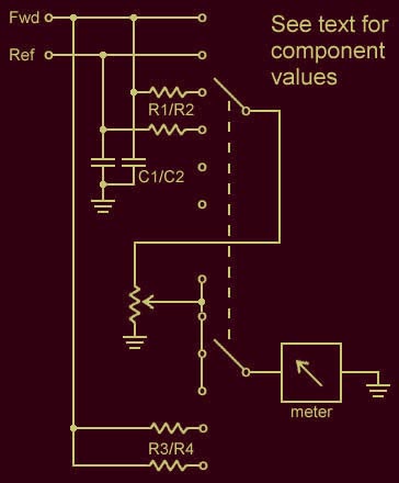
| The wiring inside the box is shown at left. The two direct inputs are used for low power while those with resistors R1/R2 allow for higher powers. R1 and R2 need to be matched. This can be done by measuring several from the same batch. Their values will depend on your choice of meter. You may have to play around with the values. Capacitors C1 and C2 bypass any RF to ground and can be almost any value around 1nF and preferably ceramic. The potentiometer value will also depend on your choice of meter but one with a value ten times the coil resistance of the meter works well. Resistors R3/R4 are used with an RF probe (details later) which also plug into the 3.5 socket but using a mono plug. R3 and R4 are different values calculated and adjusted for RF volts (10 and 100). Their values will also depend on your choice of meter. Once the values were determined and mounted onto the switch contacts, a new front to the meter similar to the one shown here can be made with a paint program, printed and stuck to the front of the meter. The front cover usually comes off with ease. Details of meter deflection and SWR are given below. (The one shown is for a simple meter with a SPDT switch for SWR only).
|
ADJUSTMENT
If you have done a very good job with the gap between the central strip line and the side pickup strips, the meter should read reasonably into a 50 ohm dummy load. That is, one way should read full scale and the other zero. It should also read well into quite high and low resistive dummy loads. A 10 ohm resisitive load should still read nearly 1:1 SWR as should a few hundred ohms RESISTIVE because we are trying to measure STANDING WAVE RATIO NOT IMPEDANCE. Of course, by the time you get to short or open circuits, both forward and reflected should be the same and half way up the meter, or thereabouts.
Calibration is simple. Work the meter using a few watts into an open circuit from the signal attenuator at the top of the page so you don't blow up the radio. Both FORWARD and REFLECTED, need to be the same so if one picks up better, it will have a higher reading. The best way to adjust the meter is to help the low reading strip along OR scrape away some copper from the better one. I adjusted mine by adding a bit of solder and helping the low reading strip along by making it thicker. ALLOW THE SOLDER TO COOL PROPERLY BEFORE CHECKING BECAUSE THE TEMPERATURE ALSO CHANGES THE READING.
FINAL CHECK
Once you have the meter reading correctly into an open circuit and dummy loads, turn the meter around ie. replace the input for the output and vice versa. It should read the same except FORWARD and REVERSE are the other way around. Lastly, make a simple 1/4 wave antenna out of a piece of wire and try it. If you make it obviously too long then snip bits off the meter should reflect the changes.
SWR VALUES FOR METER DEFLECTION
First figure of pair is SWR. Second is percentage of meter deflection.
1.0 0.0 | 1.1 4.8 | 1.2 9.1 | 1.3 13.0 | 1.4 16.7 | 1.5 20.0 | 1.6 23.1 | 1.7 25.9 | 1.8 28.6 | 1.9 31.0 | 2.0 33.3 | 2.2 37.5 |
2.4 41.2 | 2.6 44.4 | 2.8 47.4 | 3.0 50.0 | 3.5 55.6 | 4.0 60.0 | 4.5 63.6 | 5.0 66.7 | 6.0 71.4 | 7.0 75.0 | 8.0 77.8 |
9.0 80.0 | 10 81.8 | 12 84.6 | 14 86.7 | 16 88.2 | 18 89.5 | 20 90.5 | 25 92.3 | 30 93.5
Pages served from this site for 2012 - 54319

All text and images on this site are Copyright to John Langsford (vk5ajl).
You may provide links on other sites or use the information and pictures for your own personal use.
You may use the text or images for redisplay or quotation provided you acknowledge the source ie. vk5ajl.com.
I think that's pretty fair, don't you?